
Wire Bonding 101: Ball vs Wedge
Learn the fundamentals of wire bonding in semiconductor packaging, comparing ball bonding and wedge bonding methods, their processes, advantages, limitations, and ideal applications.
Kiran
1/5/20265 min read
Wire bonding remains one of the most widely used and trusted interconnection technologies in semiconductor packaging. Despite the rapid growth of advanced packaging approaches such as flip-chip, fan-out, and hybrid bonding, wire bonding continues to dominate large segments of the market due to its proven reliability, process flexibility, and cost effectiveness.
At the core of wire bonding technology are two primary methods: ball bonding and wedge bonding. While both serve the same fundamental purpose—electrically and mechanically connecting a semiconductor die to its package—they differ significantly in materials, equipment, process mechanics, and application suitability.
This article provides a comprehensive introduction to wire bonding, with a detailed comparison of ball bonding vs. wedge bonding, explaining how each process works, where it is best applied, and what trade-offs engineers must consider when selecting one over the other.
What Is Wire Bonding?
Wire bonding is a backend semiconductor assembly process in which fine metal wires are used to create electrical connections between a chip’s bond pads and the package leads or substrate. These wires typically range from 15 µm to over 75 µm in diameter, depending on application requirements.
Wire bonding serves several critical functions:
Electrical signal transmission
Power delivery
Mechanical compliance between die and package
Thermal stress accommodation
The process is valued for its adaptability across a wide range of devices, from simple analog ICs to complex multi-die modules.
Overview of Ball Bonding and Wedge Bonding
Wire bonding technologies are generally classified by how the wire is attached to the bond pads and leads.
Ball bonding uses a free-air ball formed at the end of the wire, typically bonded using heat and ultrasonic energy.
Wedge bonding uses a wedge-shaped tool to form bonds through ultrasonic energy, usually without forming a ball.
Each method has distinct characteristics that influence throughput, material compatibility, pad layout flexibility, and long-term reliability.
Ball Bonding Fundamentals
How Ball Bonding Works
Ball bonding, also known as thermosonic ball bonding, begins by forming a small molten ball at the end of a metal wire using an electrical flame-off (EFO) process. This ball is pressed onto the bond pad using a combination of force, heat, and ultrasonic energy, creating the first bond (the ball bond).
After the first bond is made, the wire is extended to the second bond site, where a stitch or wedge-like bond is formed. The wire is then clamped and broken, and the cycle repeats.
Materials Used in Ball Bonding
Ball bonding is most commonly performed using:
Gold (Au) wire
Copper (Cu) wire
Palladium-coated copper (PCC) wire
Aluminum wire is generally not used in ball bonding because it does not form reliable free-air balls.
Key Process Characteristics
Requires elevated temperatures (typically 150–250°C)
Uses ultrasonic energy and pressure
Highly automated and fast
Typically performed in a single bonding direction
Ball bonding is known for its high throughput and excellent consistency, making it the dominant method for high-volume consumer and automotive semiconductor packaging.
Advantages of Ball Bonding
High Throughput and Productivity
Ball bonding machines are optimized for speed, with cycle times that support high-volume manufacturing. This makes ball bonding particularly attractive for cost-sensitive applications.
Strong, Reliable First Bonds
The ball bond provides a large contact area, resulting in strong metallurgical bonds when properly formed. This contributes to good electrical performance and mechanical robustness.
Broad Industry Adoption
Ball bonding is widely supported by equipment vendors, material suppliers, and process ecosystems, making it easier to scale and qualify.
Limitations of Ball Bonding
Pad Layout Constraints
Ball bonding typically requires bond pads arranged to accommodate a vertical bonding approach. Very fine-pitch or staggered pad layouts can be challenging.
Temperature Sensitivity
Because ball bonding relies on heat, it may not be suitable for temperature-sensitive devices, substrates, or advanced materials.
Material Compatibility
Ball bonding is not well suited for aluminum metallization without special surface treatments, which limits its use in certain legacy or specialty devices.
Wedge Bonding Fundamentals
How Wedge Bonding Works
Wedge bonding uses a wedge-shaped tool to press the wire directly onto the bond pad using ultrasonic energy, pressure, or a combination of both. Unlike ball bonding, no free-air ball is formed.
The process typically creates a first wedge bond, loops the wire to the second bond site, and forms another wedge bond. The wire is then terminated and cut.
Materials Used in Wedge Bonding
Wedge bonding supports a wider range of wire materials, including:
Aluminum (Al) wire
Gold (Au) wire
Copper (Cu) wire
Aluminum wedge bonding is especially common in power devices and legacy semiconductor applications.
Key Process Characteristics
Often performed at or near room temperature
Relies primarily on ultrasonic energy
Allows bonding in multiple directions
Slower cycle times compared to ball bonding
Wedge bonding is valued for its precision and flexibility rather than speed.
Advantages of Wedge Bonding
Superior Pad Layout Flexibility
Wedge bonding allows bonding in any direction, making it ideal for:
Fine-pitch pads
Staggered or irregular pad layouts
Dense multi-row bond pad designs
Lower Thermal Budget
Because wedge bonding can be performed without elevated temperatures, it is suitable for temperature-sensitive substrates and devices.
Compatibility with Aluminum Metallization
Aluminum wedge bonding remains a standard for many power, analog, and industrial semiconductor devices.
Limitations of Wedge Bonding
Lower Throughput
Wedge bonding is inherently slower than ball bonding due to mechanical constraints and directional movement, which can increase cost at high volumes.
Tool Wear and Maintenance
Wedge tools experience wear over time, particularly when bonding harder wire materials, requiring careful monitoring and replacement.
Operator and Process Sensitivity
Wedge bonding can be more sensitive to process setup and operator expertise, especially for ultra-fine wires or advanced applications.
Ball vs. Wedge Bonding: Key Differences at a Glance
Process Mechanics
Ball bonding uses a free-air ball and thermosonic energy
Wedge bonding uses direct ultrasonic bonding without a ball
Wire Materials
Ball bonding: Au, Cu, PCC
Wedge bonding: Al, Au, Cu
Temperature Requirements
Ball bonding: Elevated temperature
Wedge bonding: Room temperature or slightly elevated
Throughput
Ball bonding: High
Wedge bonding: Moderate to low
Layout Flexibility
Ball bonding: Limited
Wedge bonding: High
Application-Driven Selection Criteria
Choosing between ball bonding and wedge bonding is rarely about which technology is “better.” Instead, it depends on application-specific requirements.
Consumer Electronics
High-volume consumer devices often favor ball bonding due to:
Cost efficiency
High throughput
Mature supply chains
Automotive and Industrial Electronics
These sectors often use a mix of both technologies. Wedge bonding is common in power modules and sensors, while ball bonding is used in control and logic devices.
Power Semiconductors
Power devices frequently rely on aluminum wedge bonding because of:
High current handling capability
Robust mechanical performance
Compatibility with thick aluminum metallization
Reliability Considerations in Wire Bonding
Reliability is a key consideration in wire bond selection.
Common Failure Modes
Heel cracks
Wire lift-off
Intermetallic growth
Corrosion
Fatigue due to thermal cycling
Both ball and wedge bonding can achieve high reliability when properly designed and controlled, but each has different sensitivities.
Environmental and Thermal Stress
Ball bonds may be more sensitive to intermetallic growth at elevated temperatures, while wedge bonds must be carefully designed to avoid ultrasonic damage or insufficient bonding energy.
Wire Bonding in the Era of Advanced Packaging
Although advanced packaging technologies are gaining traction, wire bonding continues to play an essential role.
Reasons include:
Lower cost for many applications
Proven long-term reliability
Ability to accommodate large dies and thick metallization
Flexibility for low-to-medium volume production
Even in multi-die and hybrid packages, wire bonding is often combined with other interconnect technologies to balance cost and performance.
Process Control and Optimization
Achieving consistent wire bond quality requires tight control of:
Bond force
Ultrasonic power
Bond time
Wire loop profiles
Tool condition
Process monitoring, inspection, and data-driven optimization are essential for both ball and wedge bonding, especially as device complexity increases.
Future Trends in Wire Bonding
Wire bonding continues to evolve through:
Finer wire diameters
Improved copper wire processes
Enhanced bonding tools
Better inline inspection and analytics
These advancements ensure that wire bonding remains relevant even as packaging technologies diversify.
Conclusion
Ball bonding and wedge bonding are foundational technologies in semiconductor backend manufacturing, each with distinct strengths and limitations. Ball bonding excels in high-volume, cost-sensitive applications where speed and consistency are paramount. Wedge bonding offers superior layout flexibility, lower thermal impact, and compatibility with a broader range of materials.
Understanding the differences between these two wire bonding methods allows engineers and decision-makers to select the most appropriate solution based on device requirements, production volume, reliability expectations, and cost constraints.
Far from being obsolete, wire bonding continues to adapt—proving that even mature technologies can remain essential in an evolving semiconductor landscape.
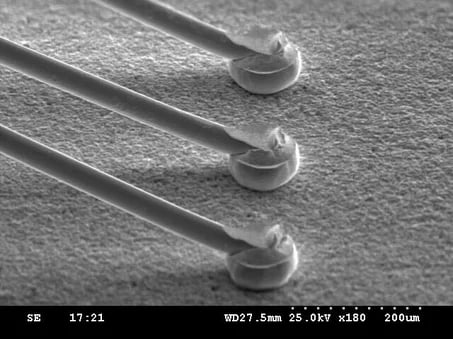
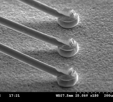
This image shows ball wire bonding used in semiconductor packaging, where spherical wire bonds form reliable electrical connections between the die and package leads.
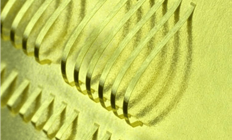
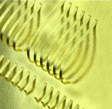
This image illustrates wedge wire bonding used in semiconductor packaging, showing fine metal wires bonded to device pads for reliable electrical interconnections.